
Designed and constructed an autonomous inverted pendulum cart system following Model-Based Systems Engineering (MBSE) principles, achieving stable pendulum equilibrium and swing-up recovery through integrated mechanical design, electronics architecture, and LQR control implementation across a nine-week development cycle.
Code: https://github.com/ItzSmudge/SysEng_coursework
Project Overview:
Developed a complete inverted pendulum cart system with a team of four engineers, progressing through requirements capture, dynamic modelling, simulation, CAD design, prototype fabrication, and experimental validation. The system integrated four drive motors, dual motor drivers, optical and incremental encoders, and an LQR controller implemented on an Arduino Giga R1, achieving stable pendulum balancing within ±0.6° and successful swing-up recovery from 5°-15° initial angles.
Systems Engineering Approach:
- V-Model Development: Structured project through MBSE phases: concept studies, preliminary design (PDR), critical design (CDR), system integration (SIR), and operational readiness review (ORR), with formal traceability between requirements and verification activities
- Work Breakdown Structure & Scheduling: Decomposed project into 12 activities with PERT three-point estimation; computed critical path (34.3 days) with activity-on-node network analysis; identified critical activities (A→B→C→D→I→J→K→L) with zero slack and calculated 99.7% probability of completion within 40-day buffer
- Risk Management: Developed failure mode and effects analysis (FMEA) with RPN prioritisation; created risk matrix across technical, schedule, and integration domains; implemented redundancy strategies (motor redundancy, sensor validation, thermal management) and security analysis for I²C communications and battery systems
- Requirements Traceability: Captured functional requirements (pendulum stabilisation, real-time data generation, adjustable initial angles) and constraints (±0.1m sprint tolerance, 0.6-1.0m pendulum length, 50g payload); verified consistency against system dynamics through parameter substitution and linearisation
Dynamic Modelling and Control Design:
- Nonlinear Dynamics Derivation: Derived coupled differential equations from Newtonian mechanics with cart mass M=1.381kg, pendulum mass m=0.168kg, length l=0.60m; resolved algebraic loops using free-body diagram analysis to eliminate unknown pivot reaction forces
- Linearisation: Applied small-angle approximations about unstable equilibrium (θ=π); proved that pendulum mass cancels from rotational dynamics under point-mass assumption, enabling robust controller tuning independent of payload changes
- State-Space Formulation: Developed 4-state model (cart position x, cart velocity ẋ, pendulum angle φ, angular velocity φ̇) with A and B matrices derived from linearised equations; verified Nyquist sampling criterion with 100Hz control loop running ~35× faster than open-loop time constant (τ≈0.35s)
- LQR Controller: Computed optimal feedback gains via Riccati equation with Q-matrix heavily penalizing angle deviation (Q₂₂=100); achieved angle gain k_θ=76.42 in simulation, perturbed to k_θ=700 on hardware to compensate for motor deadband (±200 units, 25% of full range) and structural compliance
- Swing-Up Strategy: Implemented two-stage control: open-loop jerk phase (750 units for 200-230ms) providing 10.13N impulse to swing pendulum upright, followed by 40ms coast phase, then LQR capture with 0.35rad activation threshold
Simulation and Benchmarking:
- Python OOP Simulation: Built object-oriented simulation framework with abstract base classes for controllers and filters; implemented 4th-order Runge-Kutta integration with 1ms timestep; added Gaussian sensor noise (σ=0.01rad) to observations post-integration to isolate sensor effects from physics
- Interactive Visualization: Developed concurrent simulation using Python threading and queue modules; decoupled UI thread from computationally expensive trajectory recalculation; enabled real-time slider adjustment of gains, noise levels, and disturbances with smooth animation trace
- Evaluation A – Disturbance Rejection: PID achieved superior transient performance (1.83° peak for small tap, settled <1ms) while LQR showed longer settling (1455ms for small tap) due to disabled position feedback (k_x=0); LQR used 44-48% less control effort post-settling, demonstrating cost-function trade-off
- Evaluation B – Deep Fall Recovery: PID settling times scaled linearly with angle (184ms at 5°, 281ms at 15°); LQR exhibited nonlinear degradation (214ms at 5°, 1548ms at 15°) due to linearisation validity loss at larger angles; post-settling RMS effort favored LQR (0.165-0.221N vs 0.315-0.501N for PID)
- Evaluation C – Sprint & Stop: LQR successfully completed 2m sprint in 4.78s with 5.0cm positional error and final angle 0.70°; trajectory-optimized PID failed due to hard cutoff early-exit condition, halting motor output prematurely and allowing angular momentum to destabilize the system
- Noise Robustness: Both controllers robust across hardware noise range (σ=0-0.01rad); 5-sample moving average filter reduced RMS control effort by 79% while adding acceptable 25ms phase lag; LQR cost-matrix tuning (Q₂₂=10-500) showed monotonic settling-time improvement at cost of increased effort
Mechanical Design and Fabrication:
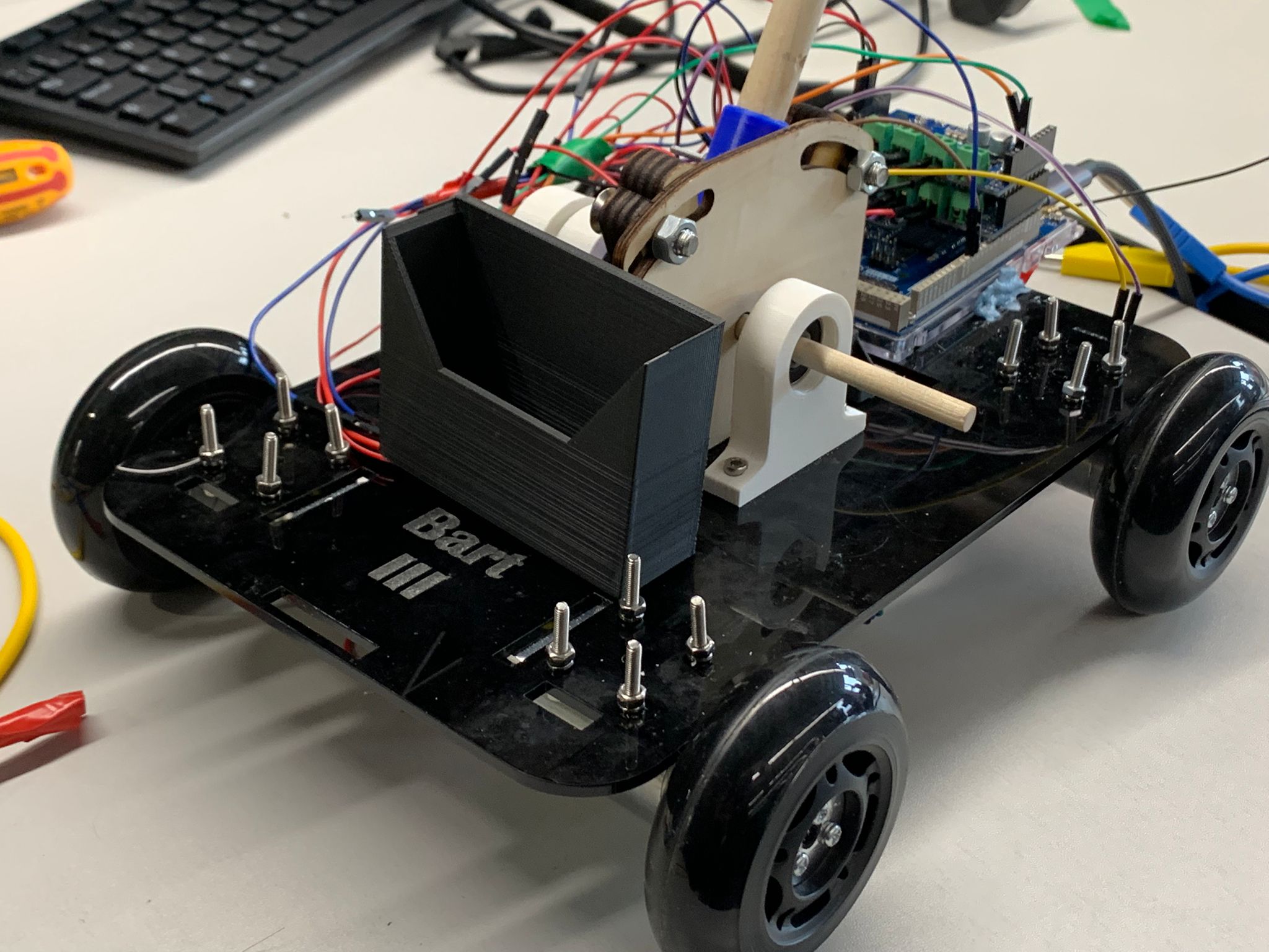
- Iterative Prototyping: Developed three cart iterations: basic wooden board (motor testing), enhanced design with 3D-printed pendulum mounts and adjustable V-holder for 5°/10°/15° initial angles, final acrylic chassis (3mm sheet) with laser-cut pendulum mount and wooden pivot dowel (6mm diameter, 15mm length)
- Pivot Assembly: Achieved damping ratio ζ=0.0038 (well below constraint ζ<0.01) through free-decay testing; logged 29 oscillation cycles from 10° to 5° over 44s; calculated natural frequency ω_n≈4.14rad/s and damping coefficient using logarithmic decrement method
- Component Selection: Integrated four Pololu 25D geared motors (1:100 reduction) with M3 and M2 fasteners, dual Motoron M3S550 drivers (I²C interface), AS22 optical encoder for pendulum angle, motor encoders for position feedback, and 50g disk payload at rod tip (point-mass model validation)
- Structural Issues: Identified high-frequency vibrations from rapid motor reversals near equilibrium; mitigated through nylock nuts and washers; remaining baseplate stress from 3mm acrylic thickness (too thin for dynamic loads) required careful assembly sequencing to avoid repeated disassembly
Hardware Implementation and Testing:
- Microcontroller Migration: Initially designed for Arduino Uno R4 (48MHz clock); migrated to Arduino Giga R1 (480MHz clock, 10× speedup) mid-project due to insufficient compute for real-time LQR and sensor processing; recovered timing issues at cost of rework and code porting
- Sensor Integration: Optical encoder (AS22) sampled at 10kHz via Ticker interrupt; motor encoders read cart position incrementally; implemented 5-sample moving average on hardware (versus 50-sample in simulation) after observing lower practical noise; discovered encoder misalignment (sensor plate micrometers too close to disk) late in tuning, requiring disassembly and realignment
- Sim-to-Real Gap: Motor deadband (25% of ±800 units) prevented small corrective forces; 10.8V supply (12% below rated 12.3V) reduced maximum corrective force; acrylic chassis and wooden dowel compliance introduced slow mechanical offset indistinguishable from angle error; angle-only control law (position gains disabled) unable to correct cart drift during balancing
- Evaluation A Results: LQR successfully stabilized pendulum upright during pre-demonstration tuning; maintained balance for several seconds before drift-driven failure; recovered from light tap perturbations; PID failed immediately, oscillating to 20° fall threshold due to integral windup and deadband prevention of small corrective forces
- Evaluation B Results: LQR jerk-to-capture handover successful at both V-block angles (5°-7° and 10°); achieved stable balancing post-capture with same temporal characteristics as Evaluation A; PID produced large oscillatory commands without convergence, failing to stabilize after jerk phase
- Evaluation C Status: Hardware LQR achieved ~1.8-2.0m sprint distance with pendulum balance maintained in pre-demonstration tuning sessions; final demonstration incomplete due to motor mount loosening under cyclic load; serial commands enabled dynamic gain scheduling (position gains activated for sprint, disabled for disturbance rejection)
Reliability and Safety Analysis:
- FMEA Prioritisation: Ranked failure modes by RPN; highest-impact risks were tight schedule (RPN=378), incorrect parameter tuning (RPN=294), and sensor noise (RPN=192); identified motor deadband and structural compliance as dominant hardware failure mechanisms post-deployment
- Reliability Metrics: Calculated system MTTF≈11.04 hours with mission-time reliability R(T_m)≈99.25% for 5-minute evaluation runs; excluding schedule risk gave hardware-only MTTF≈15.77 hours; availability A≈98.51% assuming 10-minute mean time to repair (based on observed tuning cycle times)
- Security Considerations: Identified I²C sniffing vulnerability (unencrypted motor driver commands); mitigated through physical enclosure and access restriction; analyzed battery short-circuit thermal runaway with mitigation through insulated enclosure and heat-shrink terminals; addressed Wi-Fi hijacking risk through WPA2/WPA3 encryption and token-based authentication for remote tuning commands
Key Learnings and Improvements:
- Microcontroller Selection: Early adoption of more powerful MCU (Giga vs Uno) would have eliminated mid-project porting; recommend designing mechanical interfaces around chosen MCU dimensions from inception rather than retrofitting
- Tolerancing and Assembly: Tight component spacing prioritized sustainability but hindered accessibility (e.g., impossible to extract pendulum bolt); future iterations should allocate service margins while maintaining structural integrity through better bearing support and thicker baseplate material
- Testing and Tuning Timeline: Insufficient allocation to tuning phase forced late manual gain perturbation without systematic parameter sweep; allocating 20-30% additional time would have enabled structured LQR gain optimization and discovery of mechanical issues (vibration, compliance) earlier in development
- Collaborative Workflow: RACI matrix and Miro-based visualization successfully prevented task duplication; WhatsApp coordination enabled remote CAD and algorithm development; Lean waste-reduction (TIMWOODS framework) optimized 3D printing schedules and component storage efficiency
Collaboration:
Developed with team of four engineers (Aayan Islam, Peter Neville, Helitha Cooray, and myself) across mechanical design, control systems, electronics integration, and project management. Responsibilities aligned through RACI matrix with clear accountabilities for system requirements, dynamics modelling, controller implementation, and hardware validation.
Technologies: MATLAB/Simulink, Python (NumPy, SciPy, Matplotlib), Arduino C++, LQR control, state-space modelling, CAD (Fusion 360), 3D printing, laser cutting, I²C motor drivers, optical/incremental encoders, MBSE, PERT/CPM scheduling, FMEA, object-oriented design, concurrent simulation, real-time embedded systems.