Developed an 8-state Extended Kalman Filter for real-time 2D robot localization using inertial measurement unit (accelerometer, gyroscope) and Time-of-Flight rangefinder fusion, achieving 0.03m position accuracy on straight-line trajectories and 0.03-0.11m on complex circuit paths without GPS in a bounded indoor arena.
Code: https://github.com/ashrayap-web/Sensor_fusion_coursework
Project Overview:
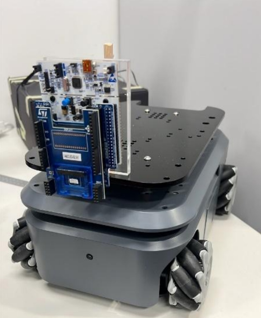
Implemented a sensor fusion state estimator for a wheeled robot operating in a 2.44m × 2.44m GPS-denied indoor arena. The system integrates accelerometer, gyroscope, magnetometer, and three Time-of-Flight rangefinders sampled at rates from 10Hz to 200Hz. The estimator tracks an 8-dimensional state vector (position x/y, velocities, accelerations, yaw, angular velocity) in the world frame using a constant-acceleration kinematic model with velocity damping and multiple robustness mechanisms to handle asynchronous sensor streams, wall-hole artifacts, and drift accumulation.
Sensor Calibration and Preprocessing:
- Gyroscope: Identified yaw axis from rotation correlation with ground-truth heading; estimated static bias (+0.00188 rad/s) and measurement noise (0.005 rad/s) from 60-second stationary dataset; discovered critical sampling rate error (104Hz vs 200Hz) that initially amplified bias integration
- Accelerometer: Decomposed 3-axis readings to extract gravity (~10 m/s²) in column 1; estimated forward (+0.028 m/s²) and lateral (-0.396 m/s²) biases; enables zero-velocity updates during stationary periods to prevent drift
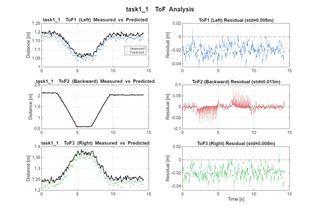
- Time-of-Flight: Determined sensor orientation mapping via comparison with expected wall distances from known start positions (physical labeling differed from functional mapping); three sensors oriented left/backward/right
- Magnetometer: Attempted hard-iron and soft-iron calibration; achieved 78° standard deviation in corrected heading, rendering it unusable; disabled entirely to prevent divergence
- Time Synchronization: All sensors upsampled to 200Hz via zero-order hold; duplicate ToF readings detected and ignored during filtering (used only for change-detection in absolute positioning)
Extended Kalman Filter Architecture:
- State Vector: [x, ẋ, ẍ, y, ẏ, ÿ, ψ, ψ̇]ᵀ in world frame; enables linear prediction between asynchronous sensor updates and preserves smooth motion propagation across 100ms ToF gaps
- Process Model: Constant-acceleration kinematic equations with velocity damping coefficient αᵥ=0.98 to absorb wheel-driven dynamics mismatch; acceleration treated as constant between updates to avoid Jacobian computation (F matrix directly equals state transition matrix)
- Measurement Model: Accelerometer/gyroscope directly sensed in world frame after rotation projection; ToF measurements use ray-casting geometry (position of robot projected along sensor bearing to find intersection with arena boundaries); numerical Jacobians only non-zero for yaw-dependent measurements (ToF)
- Prediction: State propagates via constant-acceleration model; covariance updated with process noise Q (high acceleration noise Qₐ=3.0 to absorb model mismatch)
- Update: Sequential updates from gyroscope → magnetometer (disabled) → accelerometer → Time-of-Flight sensors; Kalman gains computed from innovation covariance combining measurement noise R and predicted uncertainty
Robustness Mechanisms:
- Duplicate Detection: Zero-order-hold resampling checked against previous values; prevents applying each 10Hz ToF reading 20× at 200Hz, which would incorrectly weight stale measurements
- Angular-Rate Gating: ToF updates suppressed when |ω| > 0.3 rad/s during turns to avoid wall-hole artifacts (sensors point through wall gaps during rotation, producing erroneous range measurements)
- Innovation Gating: Measurements rejected if prediction error exceeds min(3σ, 0.8m); protects against outliers but creates trade-off (0.8m cap caused divergence during high-speed motion in task2_4)
- Zero-Velocity Updates (ZUPT): Injected pseudo-measurements (vₓ=vᵧ=0, aₓ=aᵧ=0) when |ω|<0.08 rad/s, ToF unchanged >0.2s, and accelerometer near stationary values; prevents velocity drift during stops
- Initial Heading Scan: Brute-force search at startup minimizes ToF prediction error across 360° at 1° resolution, then refines to 0.05°; achieves practical heading estimation without ground-truth initialization
Key Results and Performance Analysis:
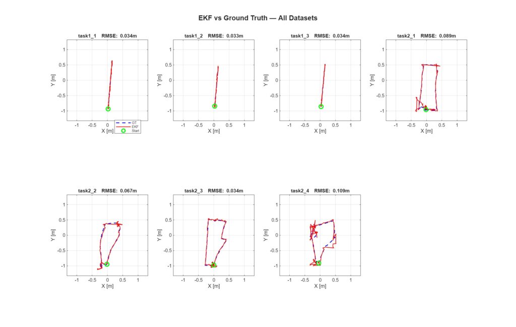
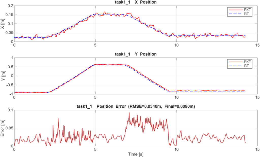
- Task 1 (Straight-line): Position RMSE 0.033m averaged across three runs; yaw RMSE 2.2°; final position error <0.04m
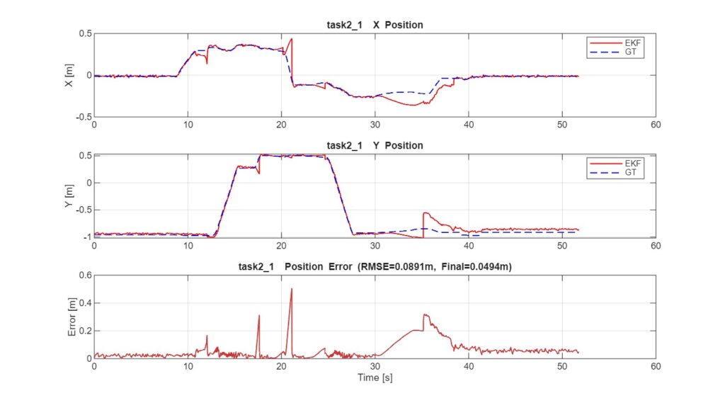
- Task 2 (Circuit course): Position RMSE 0.034-0.109m; yaw RMSE 5.0-6.9°; performance degradation driven entirely by heading drift accumulation over multiple 90° turns
- Task 2_3 (Best circuit): Achieved Task 1-level RMSE (0.034m) despite being a circuit course due to shorter path and fewer turns, demonstrating heading error is primary differentiator
- Gyroscope Bias Drift: ~6° heading error accumulated over 50-second runs; compounded position errors 2-3× from Task 1 to Task 2 as turning required integration of drifting angle estimates
Sensor Contribution Analysis:
- Straight-line segments: Time-of-Flight sensors dominate; provide absolute position corrections to arena walls; responsible for maintaining RMSE<0.04m through direct range measurements
- During turns: Gyroscope essential for real-time heading tracking; accelerometer provides contaminated centripetal signals; ToF readings suppressed to avoid wall-hole artifacts
- Stationary periods: Accelerometer enables zero-velocity detection through ZUPT; prevents velocity phantom accumulation between movements
- Largest errors: Occur in 1-2 seconds following turns before ToF re-establishes wall corrections; turn-induced heading error directly projects into position error on subsequent segments; task2_4 experienced 0.2m error spike when innovation gate (0.8m cap) temporarily rejected valid ToF corrections during high-speed motion
Failure Cases and Limitations:
- Magnetometer disabled: 78° heading standard deviation after calibration rendered absolute heading reference unusable; left system vulnerable to long-term yaw drift with only gyroscope integration
- Sampling rate error: Initial assumption of 104Hz vs actual 200Hz amplified gyroscope bias integration; critical calibration mistake discovered through trajectory deviation analysis
- Task 2_4 divergence: Fast full-arena traversal combined ToF suppression during turns with innovation gating, creating correction blackouts and forcing gate widening; heading reacquisition feature disabled after producing catastrophic jumps from local minima
- Wall-hole artifacts: Sensor field-of-view sweeps through arena wall holes during rotation; required angular-rate suppression to avoid erroneous 0.05-2.5m range readings
Trade-offs and Design Decisions:
- Model mismatch: Constant-acceleration assumption mismatches wheel-driven non-linear dynamics; addressed through high process noise Qₐ=3.0 and velocity damping αᵥ=0.98
- Heading-only correction: Gyroscope provides relative heading changes (integrates bias/drift); ToF provides absolute position but not absolute heading during turns; no usable absolute heading sensor after magnetometer failure
- Innovation gate: 0.8m cap prevents outliers but creates agility trade-off (tight gating protected against noise, loose gating allowed divergence during high-speed motion)
- State representation: 8-state vector preserves acceleration state for smooth propagation between 100ms ToF gaps; requires careful tuning of process noise to balance responsiveness vs stability
Technologies: MATLAB, Extended Kalman Filter, sensor fusion, inertial measurement (accelerometer, gyroscope, magnetometer), Time-of-Flight rangefinding, state estimation, ray-casting geometry, zero-velocity updates, Kalman gain computation, measurement gating, kinematic modelling